What Is a Single Stage Pump and How Does It Work?
A Single Stage Pump uses one impeller to move liquid from an inlet to an outlet. Its design is simple, familiar, and widely used in water systems, irrigation, heating, and industrial circulation. The pump motor turns the impeller inside a casing. Rotating blades accelerate the liquid and create pressure for discharge. At the suction side, lower pressure draws more liquid into the casing. At the discharge side, the casing slows the flow and converts velocity into useful pressure.
It sounds straightforward. Real installations are less forgiving. Air leaks, poor alignment, blocked strainers, or incorrect rotation can quickly reduce performance. A technician should check the pump curve, flow rate, head, fluid temperature, and motor load before selecting equipment. Manufacturer instructions and recognized engineering practices remain essential for safe operation. A pressure gauge may reveal unstable flow, while unusual vibration can indicate cavitation or bearing problems. These details matter more than a sales brochure’s maximum rating. That rating may describe ideal laboratory conditions, not a dirty site with long pipe runs.
This guide explains how a Single Stage Pump works, how its main components interact, and where its limits appear. It also considers efficiency, maintenance, installation quality, and practical troubleshooting. No pump is perfect. A smaller unit may waste energy when forced beyond its duty point, while an oversized unit may cycle unnecessarily. Understanding those trade-offs helps engineers, operators, and facility owners make decisions based on measured conditions rather than assumptions. Reliable results come from careful selection, correct installation, and regular inspection.
Definition and Core Purpose of a Single-Stage Pump
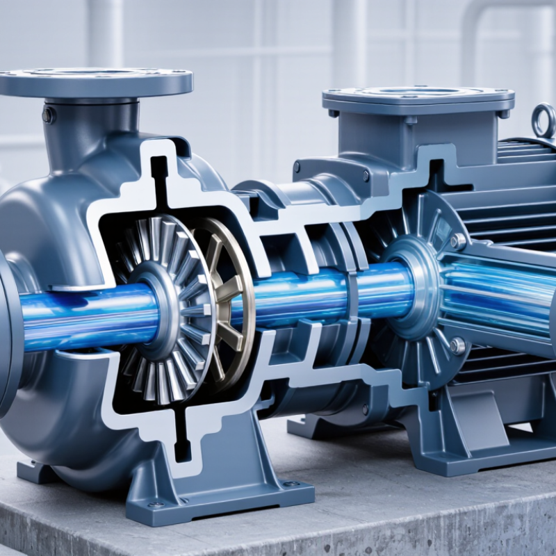
A single-stage pump is a pump built around one impeller. Its core purpose is straightforward: move liquid from one location to another while creating useful pressure. The impeller adds velocity to the liquid. The casing then converts part of that velocity into pressure. This design suits many water supply, cooling, irrigation, and process duties. It is usually selected when moderate pressure is enough.
The working sequence is simple. Liquid enters near the impeller eye, then moves outward as the impeller rotates. Centrifugal force guides the flow into the casing and toward the discharge pipe. Flow rate depends on impeller diameter, rotation speed, pipe resistance, and liquid properties. A pump curve matters here. A pump that looks suitable on paper may perform poorly after installation.
Energy use deserves attention. The U.S. Department of Energy’s Improving Pumping System Performance sourcebook reports that pumping systems can represent about 25% of industrial electricity consumption. That figure makes correct sizing more than a technical detail. Oversized pumps often throttle flow through valves, wasting energy as heat and friction. The Hydraulic Institute’s standards also emphasize matching pump performance with system conditions.
Real systems are rarely perfect. Air leaks, clogged strainers, and worn impellers can quietly reduce output. A pressure gauge and flow check often reveal the problem faster than guesswork.
Main Components and Their Functions
What Is a Single Stage Pump and How Does It Work?
A single stage pump uses one impeller to move liquid from suction to discharge. The impeller is the working heart. As it rotates, curved blades accelerate the fluid and create velocity. The casing then converts much of that velocity into pressure. It is not complicated. Yet small design errors can cause noise, heat, or unstable flow.
The main components each have a practical duty. The casing guides liquid and contains pressure. The impeller transfers mechanical energy into the fluid. The shaft carries torque from the motor. Bearings support rotation and control vibration. A mechanical seal limits leakage around the shaft, while wear rings reduce internal recirculation. In field inspections, a loose coupling or blocked strainer can look like a pump failure. Sometimes, the pump is innocent.
The U.S. Department of Energy’s Improving Pumping System Performance guidance reports that pumping systems can represent about 25% of industrial energy use. This figure explains why component condition matters beyond maintenance. A damaged impeller increases hydraulic losses. Poor alignment raises bearing loads. Oversized pumps often operate far from their best efficiency point.
The Hydraulic Institute’s efficiency guidance emphasizes matching pump performance with system demand, rather than selecting capacity by habit. Operators should check flow, pressure, vibration, seal condition, and motor current together. One reading rarely tells the whole story.
How a Single-Stage Pump Operates Step by Step
What Is a Single Stage Pump and How Does It Work?
A single-stage pump uses one impeller to move liquid from suction to discharge. Its operation follows a practical sequence. The motor turns the shaft, and the shaft rotates the impeller inside the casing. Liquid enters through the impeller eye, near the center. Rotating blades accelerate the liquid outward. The casing then converts much of that velocity into pressure. Finally, the pressurized liquid exits through the discharge nozzle.
The sequence looks neat on paper, but real pumps rarely behave perfectly. Pipe friction, liquid temperature, trapped air, and a partially closed valve can change performance. The U.S. Department of Energy reports that pumping systems may consume 25–50% of industrial electricity in some facilities. Correct sizing therefore matters. A pump that is too large may waste energy through throttling. A pump that is too small may run continuously and overheat. The Hydraulic Institute’s engineering guidance also emphasizes checking flow, head, efficiency, and net positive suction head before selection.
Tips: Keep the suction line short and airtight. Prime the pump when required. Check vibration, noise, seal leakage, and motor current during operation. A rough humming sound may indicate cavitation, not normal wear. Impeller damage can begin before the pressure gauge clearly warns you. Rechecking the system after installation is wise, because calculated conditions often differ from field conditions.
Common Types and Practical Applications
A single stage pump uses one impeller to move liquid from the suction port to the discharge port. As the impeller spins, its curved blades create lower pressure near the center. Liquid enters there, gains velocity, and leaves through the outer edge. The pump casing then converts much of that velocity into pressure. The design is simple, compact, and usually easier to maintain than a multistage pump.
Common types include centrifugal end-suction pumps, close-coupled pumps, and vertical inline pumps. End-suction models suit water transfer, irrigation, cooling circuits, and general process work. Close-coupled units save space in small workshops and building systems. Vertical inline pumps fit heating and air-conditioning loops because their pipe connections can reduce floor space. In my experience, selecting the pump by flow rate alone causes trouble. Required head, liquid temperature, viscosity, and suction conditions matter just as much. A pump can look powerful but still perform poorly with a restricted inlet.
Tips: Check the suction pipe for air leaks and sharp bends. Keep a visible pressure gauge near the discharge side. Never run a centrifugal pump dry. Inspect seals when leakage appears, even if the motor sounds normal. Oversizing is another common mistake; it may waste energy and create unstable flow. A small calculation error can become a noisy, expensive problem. Regular cleaning helps, but inspection records are often forgotten. That weakens otherwise careful maintenance.
What Is a Single-Stage Pump and How Does It Work?
A single-stage pump uses one impeller to transfer liquid by converting mechanical energy into fluid pressure and flow. The chart compares typical hydraulic-efficiency ranges for common single-stage centrifugal pump configurations.
End-suction pumps are widely used for water supply and general circulation. Inline pumps are common in heating, ventilation, and air-conditioning systems. Split-case pumps are selected for higher-flow municipal and industrial duties, while vertical turbine pumps are often used for deep wells and raw-water intake. The values shown are typical engineering ranges; actual efficiency depends on pump size, speed, liquid properties, and operating point.
Advantages, Limitations, and Maintenance Needs
What Is a Single Stage Pump and How Does It Work?
A single stage pump uses one impeller to move liquid from suction to discharge. The rotating impeller increases the liquid’s velocity. The casing then converts much of that velocity into pressure. This design suits clean water, light industrial fluids, and moderate-pressure systems. Its construction is relatively simple. Fewer internal parts can mean easier servicing and lower initial costs.
The main advantage is dependable operation when the duty matches the pump’s capacity. It can deliver steady flow without the complexity of multiple impellers. However, one impeller cannot produce extremely high head efficiently. Performance may decline with thick liquids, abrasive particles, or poorly designed piping. Cavitation is another risk. A rattling sound, unstable pressure, or damaged impeller edges may signal insufficient suction conditions. Simple does not mean careless.
Maintenance should begin with safe isolation and a check of the pump’s operating records. Inspect seals for drips, bearings for unusual noise, and couplings for misalignment. Clean suction strainers before debris restricts flow. Check vibration and discharge pressure during normal operation. Lubricate only as specified for the equipment. Running the pump dry can damage seals within minutes. Excessive tightening can also create problems. This is an easy mistake. Regular inspections are useful, but inspection results still need honest interpretation when temperature, fluid properties, or pipe conditions change.